Toyota Throttle Position Sensor Wiring Diagram
Just curious why you need these signal output? Here is a video on how to test a throttle position sensor with a basic multimeter, i also show you how to do this without a wiring diagram.multimeter used in.
Repair Guides Electronic Engine Controls Throttle

Occasionally, the wires will cross.

Toyota throttle position sensor wiring diagram. As stated previous, the lines at a throttle position sensor wiring diagram represents wires. But, it doesn’t mean link between the cables. Also i show you how you can figure out what each wire on your sensor i.
Describe the meaning of the 2 in diagram component s. Sensor t 2 throttle position sensor v 1 vapor pressure sensor v 7 vsv (evap) v13 vsv. Wiring diagram not just gives in depth illustrations of whatever you can do, but in addition the methods you ought to stick to while performing so.
Driving with a faulty throttle position sensor will have a serious impact on fuel economy, but can also lead to lasting engine damage and dangerous situations. I'm looking for a wiring diagram that will identify the 6 wires connecting to the throttle position sensor on my 2014 tundra sr5. Throttle position sensor wiring diagram 1997 1998 ford 4 6l 5 4l toyota rav4 service manual throttle pedal position sensor repair guides diesel electronic engine controls accelerator.
These guidelines will be easy to comprehend and implement. Power source of throttle position sensor (specific voltage) m+: Throttle body connector wiring vw drive by wire diagnostic and repair checking valve control part position sensor tac circuit 01 beetle problem 1 to the ecu diagram 2004 2006 3 5l system 2007 2009 2 understanding efi process page 6 96 passat vr6 p2111 actuator replace tps audizine forums re diy or bad 2018 mercedes cls 250 p0121 tp a technical.
Toyota chaser jzx90 / soarer jzz30 ecu pinout diagram pin description wire pin description wire 45 map sensor +5v (vcc) 1 test plug 47 a/t. |p0120 2004 toyota highlander code description the throttle position sensor responds to the accelerator pedal movement.this sensor is a kind of potentiometer which transforms the throttle position into output voltage, and emits the voltage signal to the engine control module ().in addition, the sensor detects the opening and closing speed of the throttle. Each part ought to be placed and linked to different parts in…
Monitor description when the difference between the output voltages of vpa and vpa2 deviates from the standard, the ecm determines th. It is supposed to help all of the common user in building a suitable method. Understanding toyota wiring diagrams worksheet #1 1.
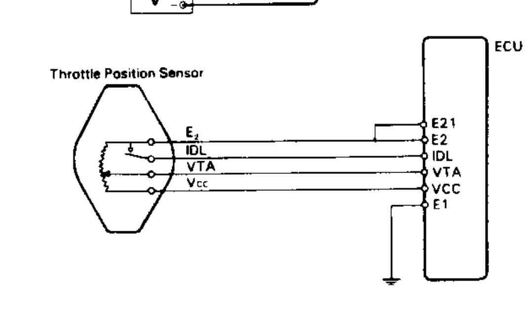
The ecm is the big blue mass at the top. Throttle position sensor signal (for engine control) vta2 :throttle position sensor signal (for sensor malfunction detection) vcta : What follows is my speculation as to how it functions:
Injunction of 2 wires is usually indicated by black dot in the junction of 2 lines. Below is a photo of the connector and the 6 wires i want to identify. Describe the meaning of the s/d in diagram component t.
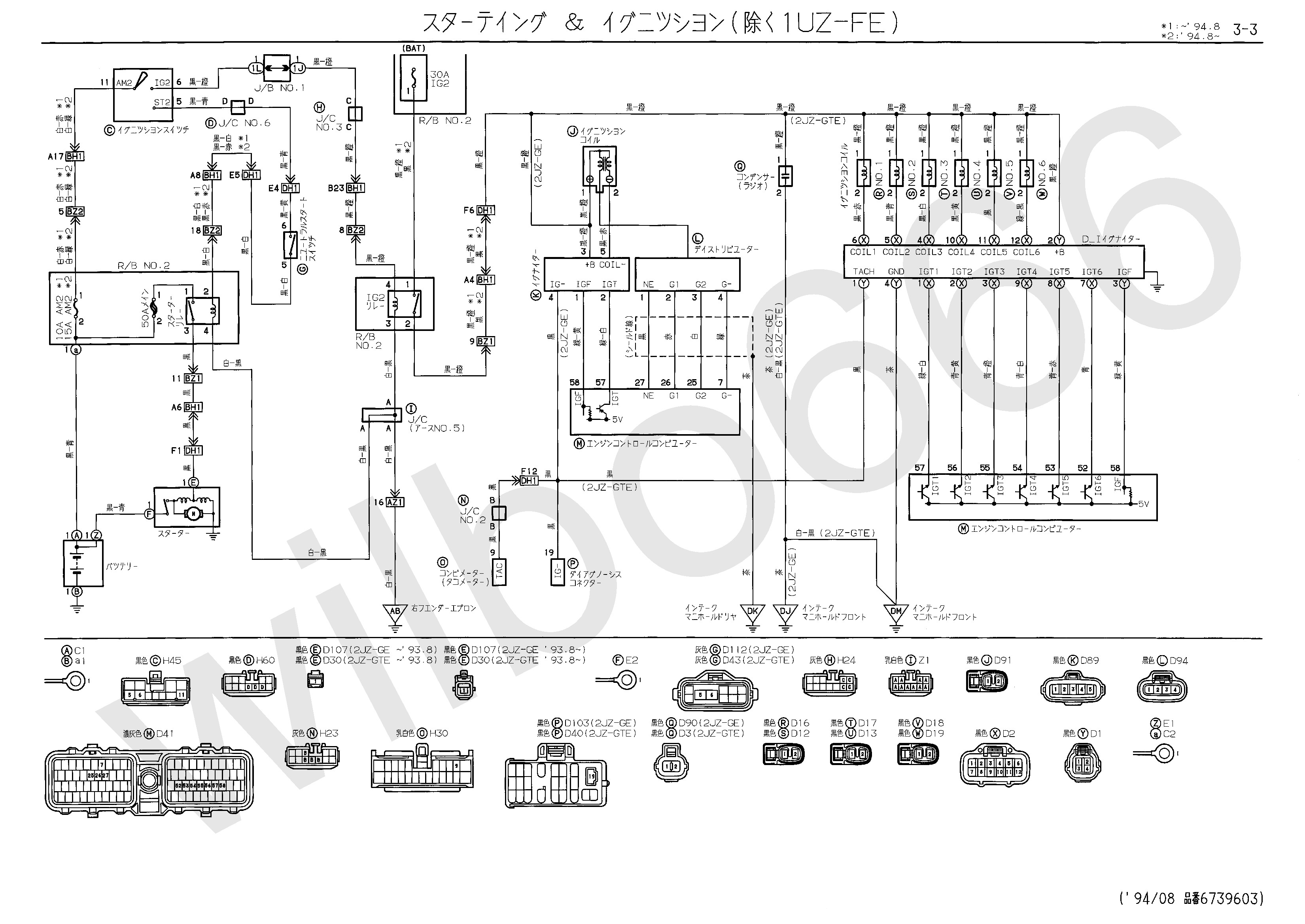
If there are any trained toyota mechanics that can correct my speculation, please chime in. Toyota 2kd ecu wiring diagram 2 toyota electrical diagram electrical wiring diagram pin on toyota toyota 1kd ftv engine repair manual rm806e pdf engine repair repair manuals repair wiring diagram ecu 2kd ftv throttle systems engineering systems engineering ecu crankshaft position sensor wiring diagram ecu 2kd ftv throttle systems engineering in. Here is a fragment of a wiring diagram that spans 13 pages.
Describe the meaning of the c13 in the diagram component q. Chevrolet throttle position sensor diagnosis and repair help. Throttle / pedal position sensor / switch d circuit range / performance description hint:
Here is a quick video on how to test a throttle position sensor tps with a multimeter. This is the repair procedure for the accelerator pedal position sensor. Wiring diagram comes with numerous easy to stick to wiring diagram instructions.
Dtc p2127/107 throttle/pedal position sensor/switch ”e” circuit low input dtc p2128/108 throttle/pedal position sensor/switch ”e” circuit high input hint: Inside the tps is a resistor and a wiper arm. There will be principal lines that are represented by l1, l2, l3, and so on.
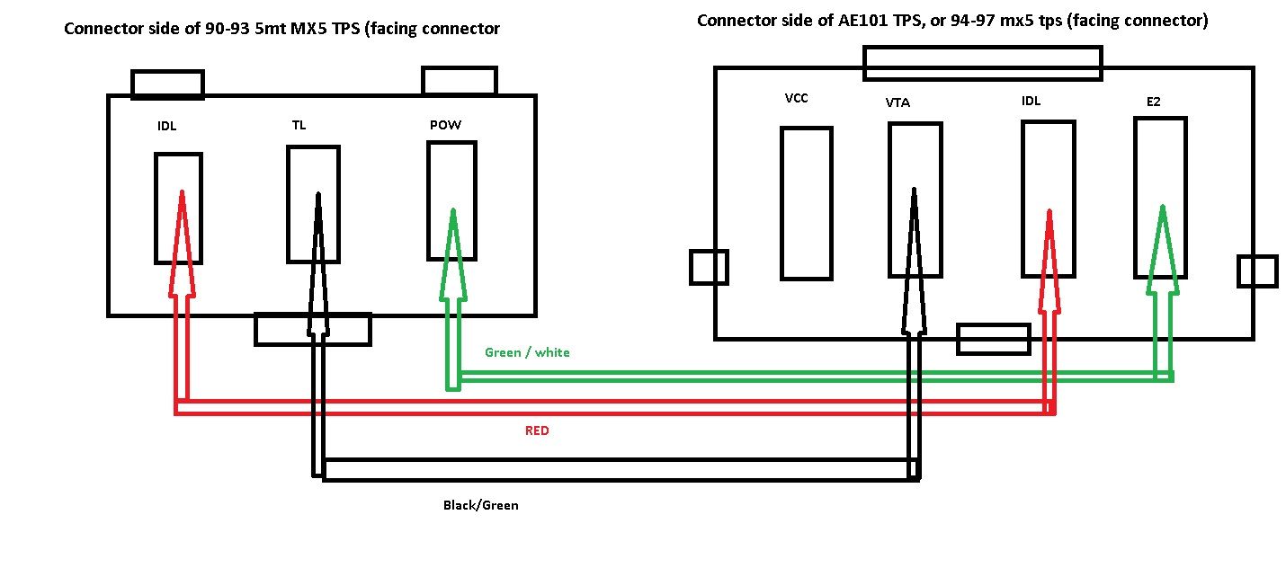
With the accelerator pedal opened more than half angle. Starting from left to right the colors or the wires are: The throttle position sensor is t1, the light blue rectangle in the lower right.
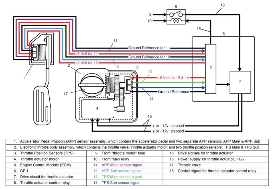
If your toyota has issues acceleration or idling issues, the throttle position sensor might be failing. Wire harness components wire harness mainly consists of wires, terminals, or housings. Throttle actuator operation signal (positive terminal) vta1 or vta2 will be your friend.
This electrical throttle system does not use a throttle cable. Describe and identify the diagram component u.
App Sensor Wiring Diagram Wiring Diagram and Schematic
Throttle Position Sensor Wiring Diagram 2004 Ford Mustang 3.9

2001 Toyota Throttle Position Sensor. CTS, Electrical, ATM

Throttle Position Sensor Out of Spec Toyota Nation Forum

Repair Guides

2003 Volkswagen Beetle Oxygen Sensor Wiring Diagram
Bmw E36 Fuse Box Diagram Bmw Throttle Position Sensor
Wiring Diagram Qg18 IKAMSAJE

Toyotum Throttle Sensor Wiring Diagram Complete Wiring
running 1.8 throttle body with 1.6 wiring? MSPNP Miata
Accelerator Pedal Position Sensor Wiring Diagram easywiring

[HH_1529] Throttle Position Sensor Wiring Diagram

[HH_1529] Throttle Position Sensor Wiring Diagram

Toyota Throttle Position Sensor Wiring Diagram Database
3Vze Knock Sensor Wiring Diagram Diagnosing And

2JZGE NaT TT Ecu Mod Page 61 ClubLexus Lexus Forum

Toyota throttle control
Repair Guides

Accelerator Pedal Position Sensor Wiring Diagram Diagram