Tachometer Wiring Schematic
Download sn79 ecm filter wiring diagram. (image/auto meter) of course, this cheat sheet only covers the tachometer’s needle movement.
smiths tachometer wiring diagram Wiring Diagram

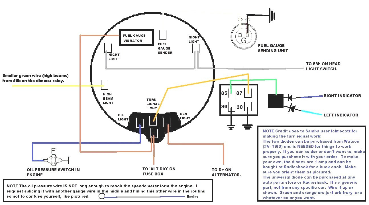
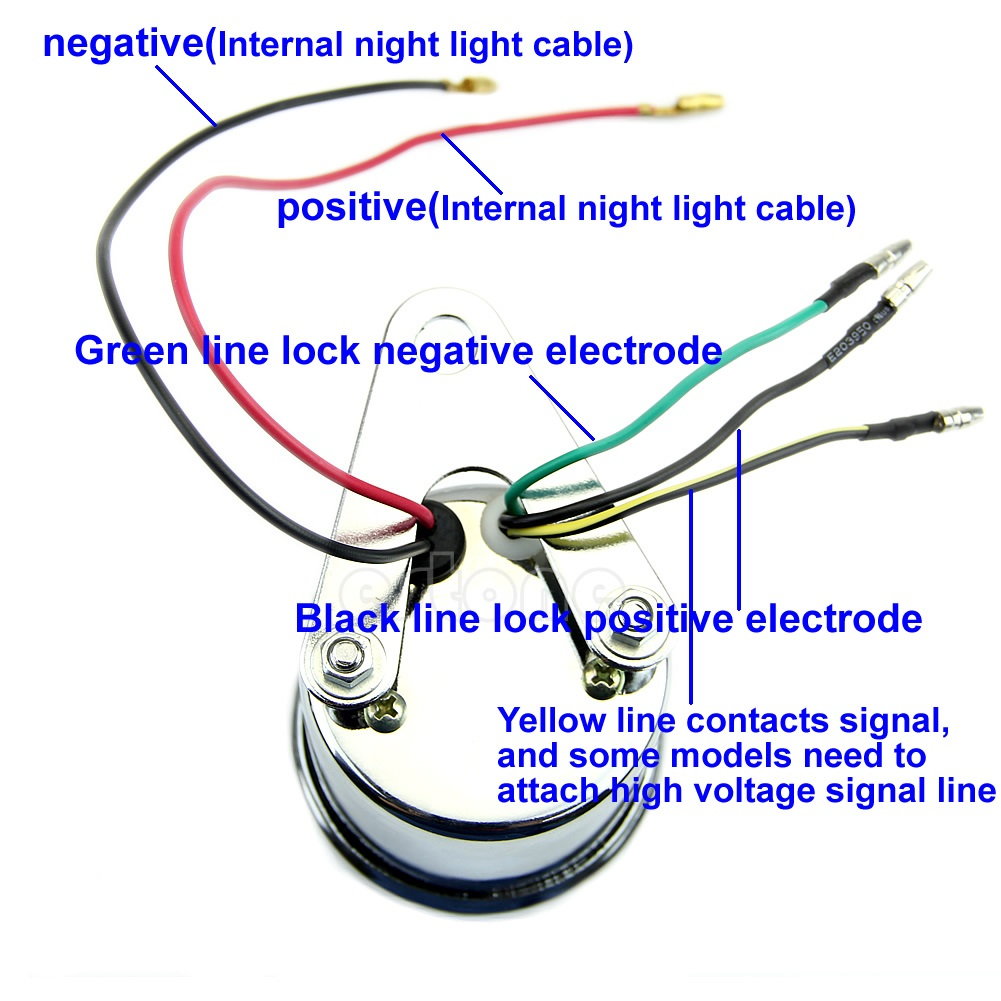
Use an existing hole in the firewall to pass the black and green wires through to the engine bay.
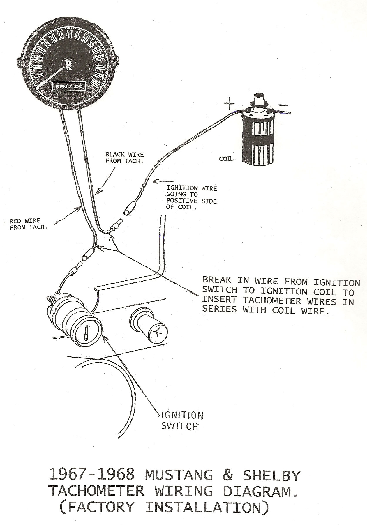
Tachometer wiring schematic. 3 tachometer wiring (figure 2): Volvo tach needle pegs with engine running its a ado technic ag 854911 signal comes from alternator should be it. 161 or equivalent 2 4.
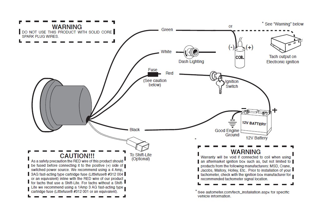
The tachometers in the diagram use a specific auto meter wiring color code, so if you’ve got a different brand of tachometer you should reference its own schematic. Sn81 sky drive gps rev 7/12/12. Volvo penta 370 general and wiring diagrams electrical materials tad720ve tad721ve.
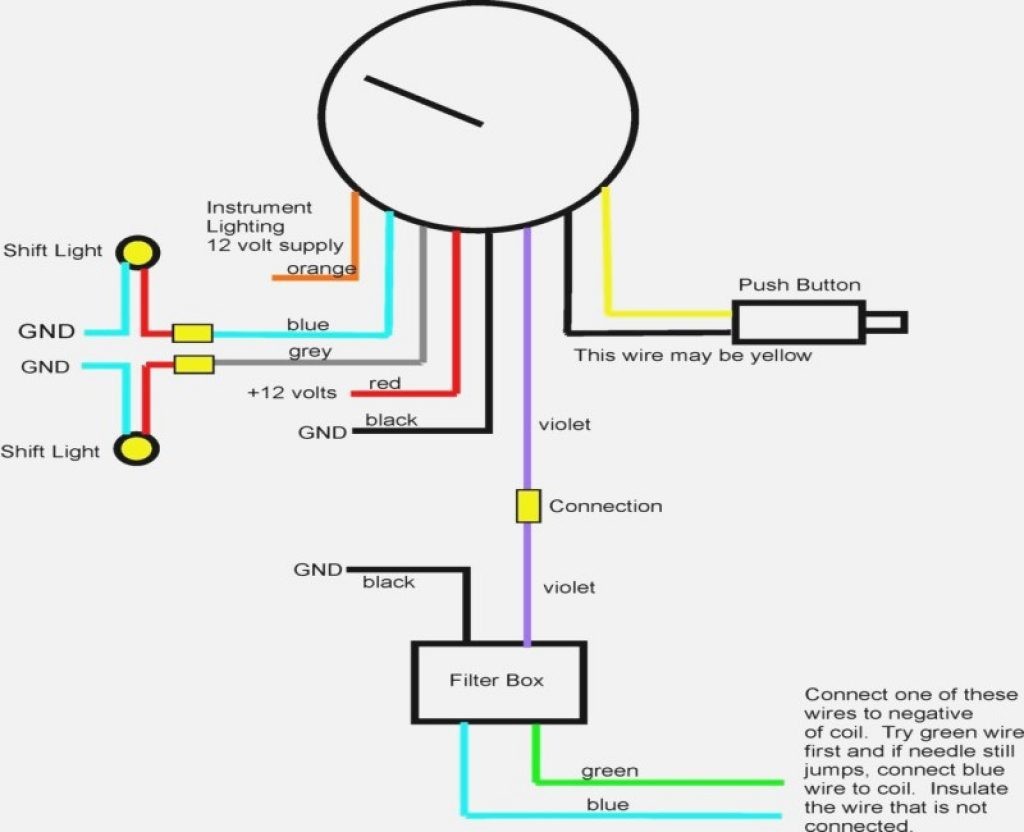
The red wire is for the ignition switch. I hooked up a 5v led with resistor. Download sn11 low volt light wiring diagram 7/12/12.
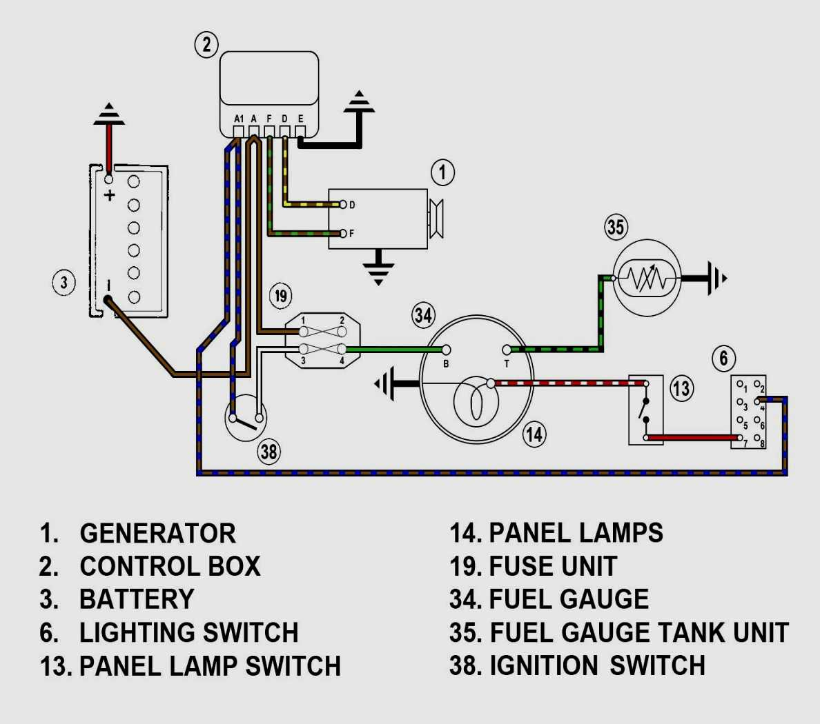
The adapter can be mounted to the fender liner, or wherever else desired. Ignition coil primary current path is shown in blue and only one polarity of white sensing wire will. There will be principal lines which are represented by l1, l2, l3, and so on.
Where does the red wire go on a tachometer? The downstream side is the side leading to the engine. Download sn76 tach adapter wiring diagram.
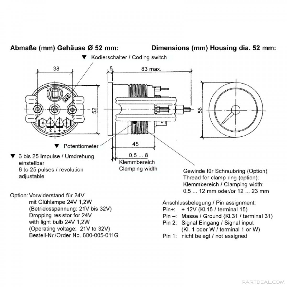
Make sure all wires are long enough to reach the necessary positive and negative terminals and any wires from the sensor. Just picked up a dixco tach at the local fleamarket today. Set the cylinder switches to match the number of cylinders in your engine.
Older dixco tach wiring help the h a m b. Existing holes will have a rubber grommet to protect the wiring. Place the tachometer in the opening and secure it with the supplied vdo spin lok clamp as shown in diagram c.
Tachometer wiring mgb gt forum mg experience forums the. Wiring connect the tachometer wires as shown. Volvo penta tachometer 23715875 was 873992 and 23715874 873998 replaces vp873688 vp873660.
Wire the tachometer to the vehicle as shown in diagram h on page 4. At times, the cables will cross. I have induced voltage from the spark plug wire and a hall sensor working.
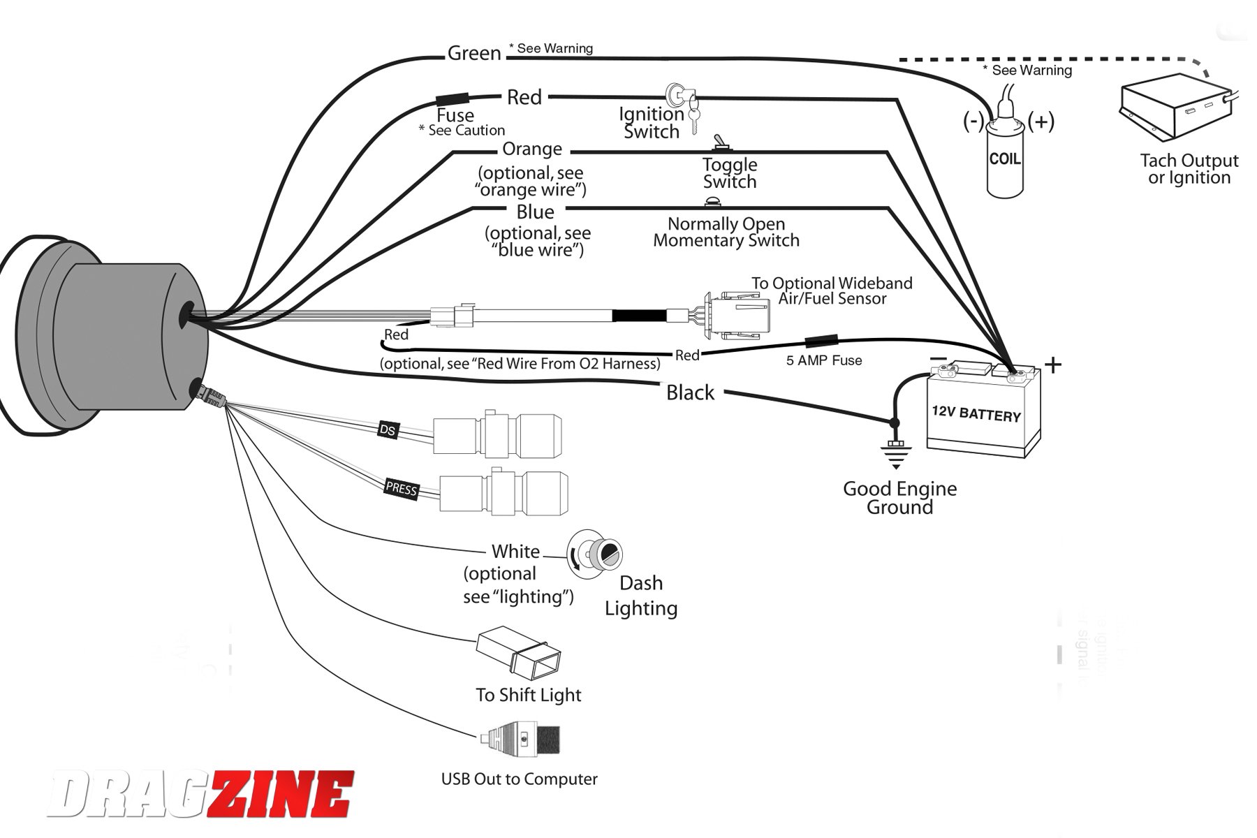
12v battery coil ignition coil tach base can be mounted in either direction for convenient mounting. Sn79 ecm filter rev 2/3/11. It consists of guidelines and diagrams for various types of wiring techniques as well as other items like lights, home windows, etc.
Yanmar tacho query cruisers sailing rev counter stopped showing revs 2gm tach forums tachometer bouncing wiring question b25 c35 panels marine 3ym30 where do i find the hour meter to gm series engines. I'm exploring the differenet ways to make a tachometer for a small one cylinder 4 cycle motor. But, it doesn’t mean connection between the cables.
Connect the wire from pin #4 to a switched +12 volt or +24 volt source. The adapter’s black wire goes to a ground point, and the gray wire to your tachometer. The wiring diagram shown is a typical installation.
Injunction of two wires is usually indicated by black dot on the intersection of 2 lines. Wire the tach adapter’s red / green wire to the downstream side of the cut red/light green factory wire. Please understand that proper wiring must be maintained throughout your vehicle.
Cut out a notch in this grommet to pass the wires through or drill a new hole for the wires to be sent. For operation on 4 or 6 cylinder engines a switch adjustment must be made. Which wire is positive green or red?
I built a full wave rectifier circuit (4 diodes). Download sn81 cruise control interrupt wiring. Wire, connect the (pos) terminal to a switched +12v source, like the ignition wire.
Tachometer installation and operations instructions. Be sure to wire the tachometer before mounting. The wiring diagram shown is a typical installation.
Connect the white wire to the inside lighting switch, which will illuminate the tachometer when the headlights are on. With the tachometer and wiring in place, finishing the job is easy. Variety of autometer tach wiring diagram.
Because the tachometer reading is based on only 1 cylinder. You may also mount the tachometer the installation, wiring, calibration and operation of all. Yanmar rev counter stopped showing revs sensor or tacho problem ybw forum.
Connecting to the ignition coil or msd 6 1. Wiring diagram for that answer. When connecting to the negative post of the ignition coil or to the msd 6 box run the shielded cablešincluded with.
Beginning with the tachometer fig. Proceed to tachometer signal hookup. Wiring diagram contains several detailed illustrations that present the relationship of varied things.
According to earlier, the lines in a tach wiring diagram represents wires. Smithsclassic sw em smith s tachometer to smiths electronic tachometers wiring vintage repair issue all about circuits need help a tach mgb gt forum mg experience forums the back of electrical instruments by lotuselan net programmable. Connect this red wire so that when the car is started the tachometer will begin operating.
My next project is to trigger off of the primary side of the coil. Refer to diagram b for dimensions. Prepare insulated ¼ spade terminals for use with the tachometer.
For chrysler blue, gold and silver boxes, ford standard electronic ignitions, and most other oem standard, cd and electronic ignitions. Vintage tachometer wiring wiring diagram pictures.
Yamaha Outboard Tachometer Wiring Diagram Free Wiring

Yamaha Outboard Tachometer Wiring Diagram Free Wiring

Rpm Gauge Drawing Free download on ClipArtMag
Motorcycle Tach Wiring Diagram Database Wiring Diagram
Autometer Pro Comp Tach Wiring Diagram Collection
Tachometer Wiring Diagram Wiring Diagram
[DIAGRAM] Proform Tachometer Wiring Diagram FULL Version
Technical Wiring an Old School Tach The H.A.M.B.
Faze Tachometer Wiring Diagram For Your Needs
Jdm Tachometer Wiring Diagram
Yamaha Outboard Tachometer Wiring Diagram Wiring Diagram
Quick question on Tach wiring Harley Davidson Forums
Tachometer Wiring

Wiring Up A 5'' Monster Tacho In Your Car Car Electrical

Vdo Marine Tachometer Wiring Diagram Wiring Diagram Schemas

Autometer Tachometer Wiring Diagram Collection
Suzuki Outboard Tachometer Wiring Images Wiring Diagram

Motorcycle Tachometer Wiring Diagram Database Wiring

Sun Super Tach 2 Wiring Diagram Cadician's Blog